
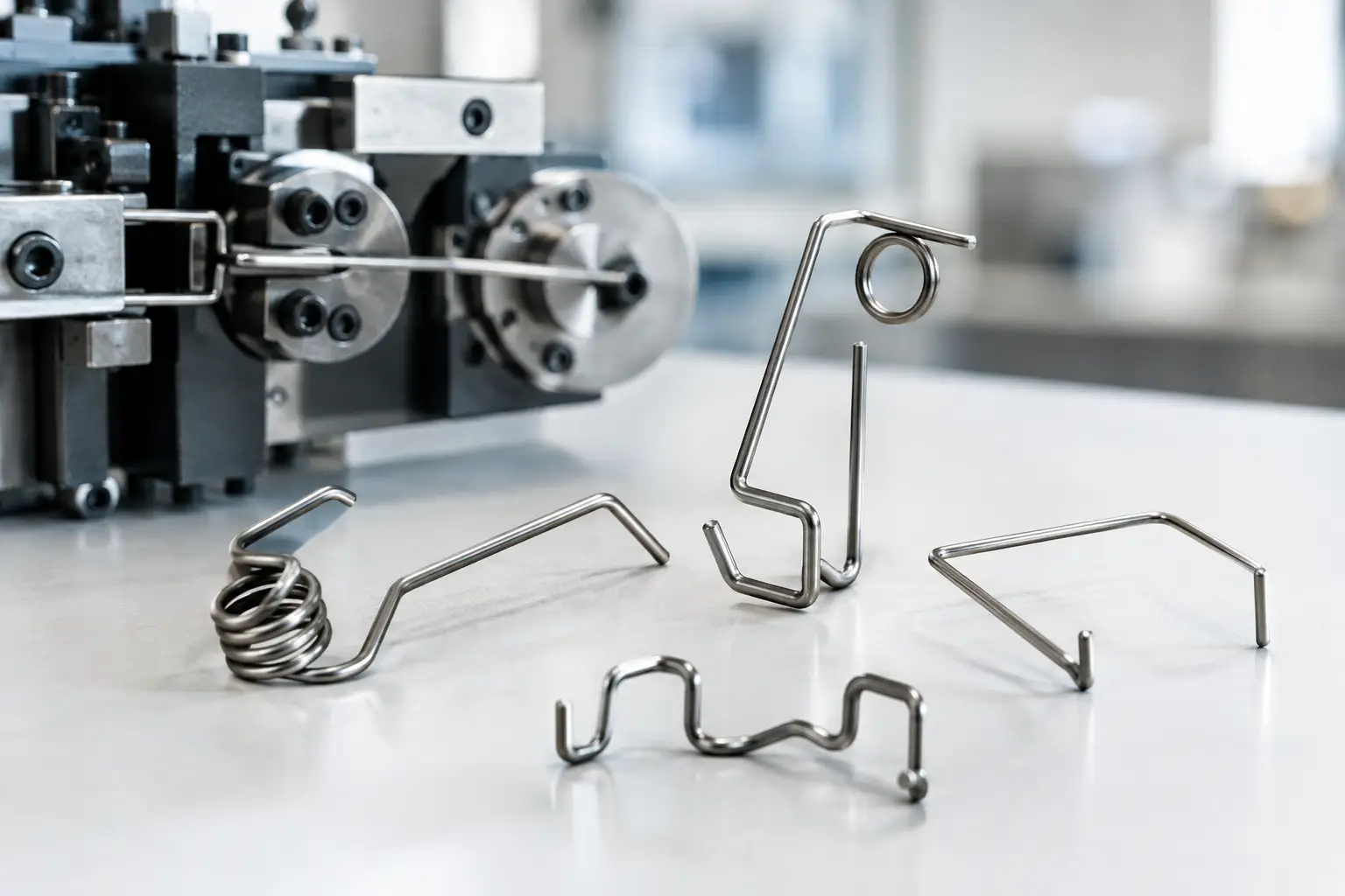
A wire form can look deceptively simple: a few bends, a loop, perhaps a tightly controlled leg length. Yet precision wire forming is often where a product’s functional reliability is won or lost. A minor variation in bend angle, springback or cut length can affect contact force, sensor position, latching behaviour, fatigue life or assembly yield. For engineers working with miniature and high-performance components, the geometry is only part of the specification. Repeatability is the real requirement.
That changes the conversation from “Can this wire be bent?” to “Can this part be manufactured consistently, inspected reliably and supplied at volume without creating downstream surprises?” The answer depends on material behaviour, forming sequence, tool design and early collaboration between the design team and the manufacturing specialist.
Why precision wire forming is more than bending wire
Wire forming converts round, flat or shaped wire into functional components through cutting, bending, coiling, stamping and secondary operations. Typical parts include clips, retainers, contact elements, pins, hooks, brackets, spring forms and miniature mechanical features. In demanding applications, these components may be measured in millimetres, but their influence on the finished assembly is substantial.
A wire form performs because of both its shape and its stored energy. This is the key distinction from a purely decorative or non-load-bearing bent component. When a clip must retain a housing through repeated cycles, or a contact must maintain a defined force over temperature changes, the forming process has to control more than dimensions. It must preserve the material properties the design relies on.
This is particularly relevant in medical devices, automotive electronics, aerospace assemblies, semiconductor equipment and sensor systems. These applications frequently combine tight packaging envelopes with high cycle demands, traceability expectations and no room for unpredictable variation.
Material choice sets the boundaries
The best forming strategy starts with the wire, not the machine. Stainless steels, carbon spring steels, copper alloys, phosphor bronze, beryllium copper and nickel alloys each respond differently to bending and stress. Tensile strength, temper, surface finish, conductivity, corrosion resistance and operating temperature all influence the final result.
Springback deserves special attention. After forming, most metals recover elastically to some degree, opening a bend or changing an angle. The amount is affected by the alloy, temper, wire diameter, bend radius and forming direction. A programme that produces the correct geometry in one material may miss it completely when a different temper or supplier batch is introduced.
For electrical contacts, selecting a material is usually a balance rather than a search for a perfect answer. Higher conductivity may be attractive, while higher strength and fatigue resistance may be needed to maintain contact force. A suitable plating can improve solderability, corrosion performance or electrical behaviour, but it also introduces thickness and adhesion considerations that must fit the forming sequence.
Material consistency matters just as much as material designation. Specifying an alloy alone is rarely sufficient for close-tolerance work. Wire diameter range, mechanical condition, coil set, surface quality and lot-to-lot control should be discussed before the design is frozen.
Tooling and forming sequence create repeatability
In precision wire forming, the order of operations is part of the engineering. Creating one bend can alter the position of another. A tight-radius feature may need to be formed before a longer leg is introduced. A cut edge may need to face away from a contact surface. And a form that appears accessible in a CAD model may be impossible to produce without tool interference.
CNC wire forming provides flexibility for prototypes and lower-to-medium volumes, especially where part geometry may evolve. Dedicated tooling can offer faster cycle times and stronger repeatability for established, higher-volume programmes. Neither route is automatically superior. The right choice depends on annual demand, dimensional requirements, validation needs, part complexity and the likelihood of design change.
Tool wear is another practical issue. Small changes in a forming point, guide or cut-off feature can gradually move a dimension out of tolerance. A capable supplier plans for this with controlled tooling materials, preventative maintenance and inspection routines rather than waiting for a production failure to reveal the problem.
Tolerances must be linked to function
Tight tolerances should be applied where they protect product performance, not simply because a drawing can carry more decimal places. Over-specification increases tooling complexity, inspection effort, scrap risk and cost. Under-specification can leave functional variation hidden until final assembly.
A useful approach is to identify the features that locate the component, create force, engage with a mating part or influence an electrical path. These are the characteristics that often justify tighter control. Less critical free-state dimensions may allow more latitude, particularly when the component is designed to flex during installation.
The measurement method also needs agreement. Complex wire forms are not always well represented by two-dimensional call-outs alone. Functional gauges, optical measurement, coordinate measurement systems and go/no-go fixtures can each have a role. Where the part interacts with another component, a functional checking fixture may tell the more useful story.
Design for manufacture starts before the first sample
Early manufacturability input often prevents the most expensive kind of redesign: the one discovered after tooling, validation or assembly trials have begun. A technical review should consider minimum bend radii, achievable leg lengths, access for tooling, burr orientation, risk of part distortion and practical methods for feeding and handling the wire form.
Very small parts add their own complications. As wire diameter decreases, surface condition becomes more influential, handling becomes more delicate and inspection can consume a meaningful share of total production time. A tiny feature may be feasible, but feasibility is not the same as stable, economical serial production.
Secondary operations should be considered as part of the complete route. Heat treatment may relieve forming stress or establish the required spring properties. Deburring can protect adjacent components and operators. Cleaning, passivation, plating, coating, overmoulding or assembly may all alter dimensions or surface performance. The correct process sequence protects the function of the part rather than treating each step as isolated.
For regulated or safety-critical products, documentation requirements need to be built in from the beginning. Material certificates, inspection records, process validation, change control and traceability can be straightforward when the production plan anticipates them. Retrofitting them later is rarely straightforward.
Common failure modes and what they reveal
A wire form that fails in service often leaves clues about the underlying process or design issue. Cracking at bends can point to an unsuitable bend radius, overly hard material, poor surface quality or a forming operation that has exceeded the material’s limits. Loss of force may indicate stress relaxation, incorrect heat treatment or an alloy poorly suited to the operating temperature.
Dimensional drift across production can be associated with tool wear, variation in incoming wire, inconsistent feed control or an inspection method that does not reflect how the part is constrained in use. Scratching or plating damage can arise from handling, guides or post-forming operations. These are not minor cosmetic concerns when surface integrity affects corrosion resistance, electrical performance or fatigue life.
The remedy is not always a tighter tolerance. Sometimes it is a revised bend radius, a different temper, a change in the datum strategy or a simple adjustment to the order in which features are formed. Good problem-solving focuses on the mechanism behind variation, not just the visible symptom.
Choosing a production partner for precision wire forming
A capable wire-forming partner should be comfortable discussing the application, not merely quoting from a drawing. Ask how they validate critical features, manage incoming material, control tooling wear and handle engineering changes. For components with a spring or contact function, ask how force, deflection and cycle performance are assessed alongside free-state dimensions.
It is also worth considering the wider component system. A wire form may sit beside a deep-drawn housing, moulded silicone feature, machined part or coated contact surface. Coordinating these interfaces early reduces tolerance stack-up issues and avoids the familiar late-stage question: why does every component meet its drawing, yet the assembly still does not work?
JVS Sales & Technical Consultants supports this kind of conversation as a local technical contact, connecting development teams with specialised manufacturing capability and coordinating the path from initial concept to production-ready precision parts. That is especially valuable when the wire form is only one small, critical element in a larger technical challenge.
The strongest wire-form projects begin with a clear view of what the component must do in the finished product. Bring the mating parts, operating conditions and functional risks into the discussion early. A well-formed wire component may be small, but it should never be treated as an afterthought.
