
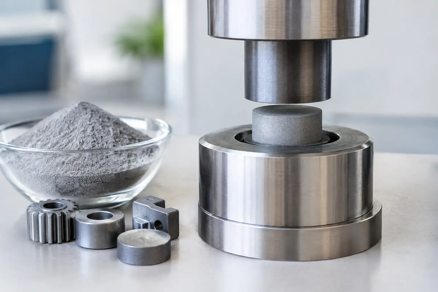
A component that begins as powder can end up in a fuel system, surgical instrument, sensor assembly or industrial drive. That transformation is not simply a pressing operation. Powder compaction is a controlled manufacturing route in which material behaviour, tool design, density distribution and thermal processing must work together to produce a part that performs reliably at volume.
For engineers, the attraction is clear: complex net-shape or near-net-shape components can often be produced with very little material waste and reduced secondary machining. For purchasing and operations teams, the question is more practical: can the process repeatedly achieve the required geometry, strength, surface condition and cost at the planned production scale? The answer depends on selecting the right compaction method early, rather than trying to force a conventional route onto an unsuitable component.
What Powder Compaction Can Achieve
Powder compaction forms loose metal, ceramic or specialist material powders into a green compact by applying controlled pressure within a die or flexible mould. The green compact has its intended shape but usually does not yet have the mechanical properties required for service. It is commonly sintered afterwards, allowing particles to bond and the component to develop strength, density and dimensional stability.
This sequence sounds straightforward. In practice, it is a balancing act. Powder must fill the cavity consistently, move predictably under pressure and release cleanly from the tool. The compaction cycle must create adequate green strength without introducing cracks, lamination or density variation. Sintering then needs to account for shrinkage, distortion and the final material specification.
Well suited parts often have relatively consistent wall sections, an axis of pressing that supports practical ejection, and features that can be formed without excessive undercuts. Typical examples include gears, bushings, valve elements, structural parts, magnetic components, filters and hard-metal or ceramic shapes. Powder routes can be particularly compelling where a conventional machined part would remove a large percentage of costly material.
However, powder technology is not automatically the best answer for every precision component. Very thin sections, sharp re-entrant geometry, extreme length-to-diameter ratios or demanding fully dense properties may call for a different process, additional secondary operations or a different compaction approach. Good manufacturability work identifies those constraints before tooling investment begins.
Mechanical and Isostatic Powder Compaction
The two broad approaches most often considered are mechanical powder compaction and isostatic compaction. They solve different manufacturing problems, and neither is universally superior.
Mechanical compaction for repeatable production
Mechanical compaction uses rigid tooling and punches to press powder in a defined die cavity. It is highly productive and can achieve excellent repeatability when part geometry, powder formulation and tooling are correctly engineered. Multi-level tooling can form features such as steps, recesses and varying heights, making it valuable for many precision production parts.
The key consideration is how pressure travels through the powder. Friction against the die wall and between powder particles can create density differences from one area to another. Double-action pressing, floating dies and carefully designed fill arrangements can help manage this, but they do not remove the physics. A component that looks simple in CAD may still be difficult to compact uniformly.
Mechanical compaction generally makes most sense where volumes justify dedicated tooling and where cycle time matters. Tooling represents an upfront commitment, so the business case should consider annual demand, product life, material savings, machining reduction and the expected maintenance strategy. It is a production technology, not just a means of making a first sample.
Isostatic compaction for complex shapes and uniform density
Isostatic compaction applies pressure more evenly around a powder-filled flexible mould. In cold isostatic pressing, the mould is subjected to fluid pressure, helping to create a more uniform green density than is practical in many uniaxial pressing applications. This can be particularly useful for larger, more complex or challenging ceramic and hard-metal preforms.
The trade-off is that the compact normally needs additional machining before or after sintering to create precise final features. Cycle times may also be less favourable than high-speed mechanical pressing. Yet for geometries that cannot be pressed economically in rigid dies, or for parts where density uniformity is critical, isostatic processing can be the more reliable route.
The best choice depends on the required material, dimensions, functional loads, tolerance zones and production forecast. A useful early question is not, “Which machine should we use?” It is, “Which process creates the most stable route from powder to approved component?” That question brings tooling, powder supply, sintering capability and quality assurance into the discussion from the start.
Designing Parts for Stable Compaction
Part design has an outsized influence on process capability. Powder does not flow like a liquid, and it does not behave like solid stock in a milling machine. Designers should therefore think about filling, pressing direction, ejection and shrinkage as part of the component geometry.
Features perpendicular to the pressing direction can be achievable, but they may require complex tooling and introduce local density challenges. Deep narrow bores, abrupt thickness changes and delicate green features also deserve scrutiny. A modest design adjustment can reduce tooling complexity, improve green strength and remove a secondary operation. Conversely, an apparently small cosmetic detail can make a compact difficult to eject or sensitive to cracking.
Tolerances require the same realism. Tight tolerances are possible, but the final result depends on the combined variation of powder, compaction, sintering and any calibration or machining stage. It is often more economical to specify tight control only on functional interfaces, while allowing sensible tolerance bands elsewhere. A critical bore may be finished after sintering; a non-critical outer profile may be formed directly in the tool.
Material selection also changes the conversation. Iron-based powders, stainless steels, nickel alloys, copper-based materials, ceramics, ferrites and hard metals each bring different compressibility, lubrication, shrinkage and sintering behaviour. Properties such as magnetic response, corrosion resistance, electrical conductivity, wear resistance and porosity must be linked to the intended application, not treated as isolated material data-sheet values.
From Prototype to Production-Ready Component
A credible powder compaction project begins with more than a drawing and a target price. The development team needs to understand the component’s function, loads, operating environment, annual volume, inspection requirements and any safety or regulatory implications. For medical, aerospace, automotive and sensor applications, traceability and process validation may be as significant as the geometry itself.
Early samples can prove material behaviour and general form, but prototype methods do not always predict serial production performance. Dedicated production tooling, controlled powder handling and production-scale sintering introduce different variables. A structured development plan should therefore include design-for-manufacture review, material trials, dimensional analysis after sintering, capability studies and a clear route for approving any secondary operations.
Quality control should focus on the characteristics that affect function. Depending on the part, that may include density, porosity, transverse rupture strength, hardness, microstructure, dimensional stability, surface finish or leak performance. Non-destructive inspection, metallography and statistical process control may all have a role. The correct inspection plan is proportionate to the risk: measuring everything is expensive, but overlooking a critical density gradient can be far more costly.
Supply continuity matters too. A powder formulation is not merely a commodity if its particle size distribution, lubricant content or chemistry directly affects compaction and sintering outcomes. Changes in material source, tool condition or furnace profile need disciplined change control. For programmes with long service lives, this is often where a technically engaged supplier relationship earns its value.
Where Technical Coordination Makes the Difference
Powder parts sit at the intersection of design engineering, materials science, tooling and production operations. A delay in one area can easily appear as a problem somewhere else: a tool issue may look like a powder issue, and a sintering variation may be mistaken for an inspection problem.
That is why JVS approaches specialised manufacturing projects as coordinated technical programmes, connecting customers with established process specialists while maintaining a local, technically fluent point of contact. The objective is not simply to quote a pressed part. It is to establish a manufacturable route that supports performance, quality and dependable supply.
If a component may benefit from powder technology, bring the functional requirements, critical dimensions and expected volumes into the conversation early. The most valuable changes are usually made before the tool steel is cut, when a practical adjustment can turn an ambitious concept into a repeatable production part.
