
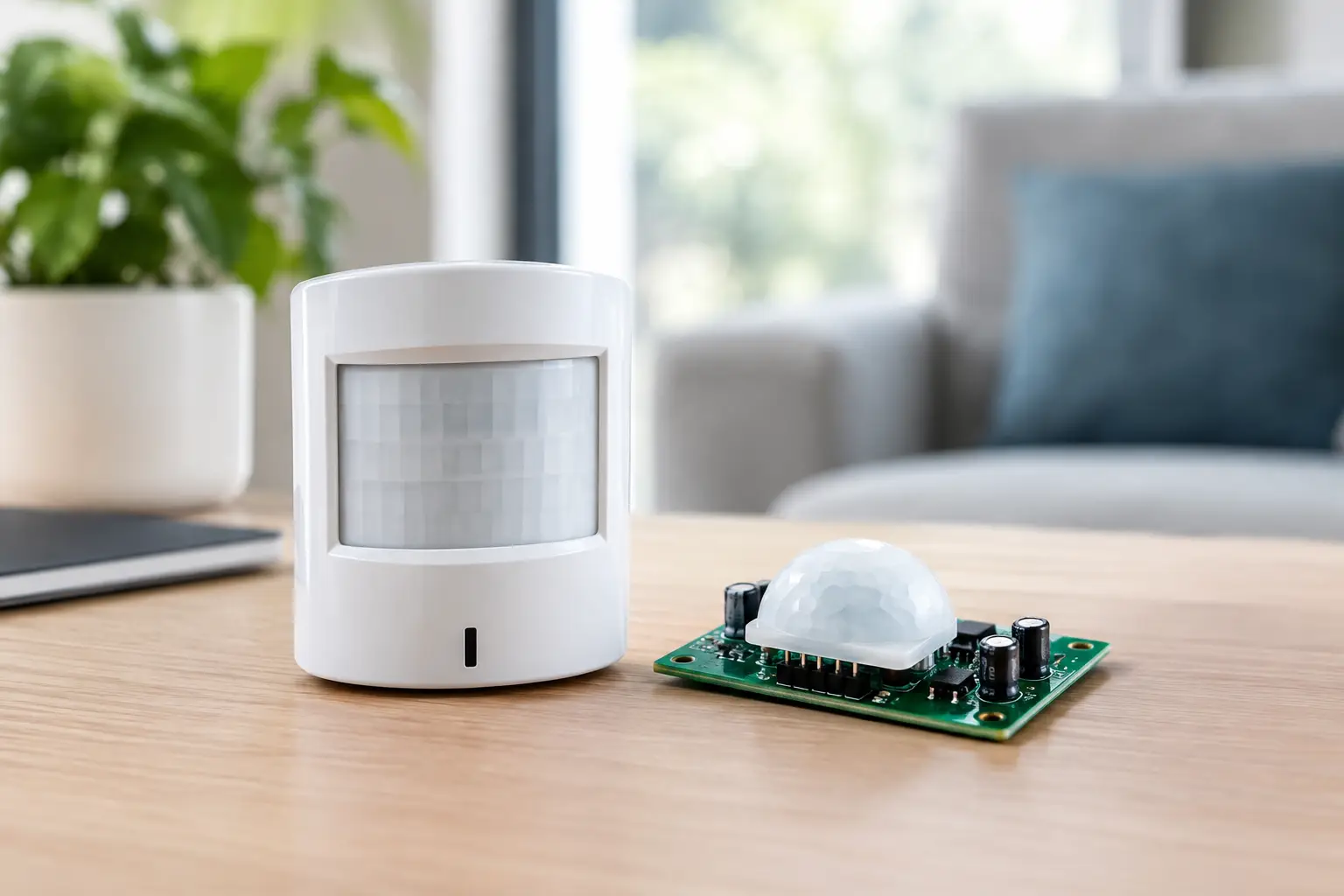
A PIR detector can look perfectly acceptable on the bench, then miss a person walking through a real corridor, trigger when a heater cycles, or lose range after the enclosure is fitted. To improve PIR sensor signal reliably, treat the sensor, lens, electronics, mechanics and application environment as one detection system. Changing only one element may increase the raw output, but not necessarily the useful signal-to-noise ratio.
For occupancy detection, people counting and intelligent lighting, the aim is not maximum sensitivity in isolation. It is dependable detection of the intended movement at the intended distance, without nuisance events, excessive current consumption or a housing that is difficult to manufacture. That requires a disciplined approach from optical specification through to production validation.
Start with the signal you actually need
A passive infrared sensor responds to changing infrared energy across its sensing elements. A person moving through the field of view creates this change because their body temperature differs from the background. The useful electrical signal is small, so every source of optical loss, thermal drift and electrical interference matters.
Before selecting a lens or adjusting gain, define the detection task in measurable terms. Is the system intended to detect a person entering a small meeting room, movement across a warehouse aisle, or the presence of someone making very small movements at a desk? These are different problems. A wide field of view may be ideal for a luminaire over a doorway but dilute the available energy over longer distances. A narrow, long-range field may offer stronger zones but leave unacceptable gaps close to the product.
Specify the target distance, mounting height, horizontal and vertical coverage, walking direction, movement speed and required detection probability. Also define what must not trigger the unit: adjacent walkways, warm machinery, sunlight patches, air outlets or passing vehicles. This application map gives the optical and electronic design team a useful target rather than a vague request for more sensitivity.
Improve PIR sensor signal with the right lens
The PIR lens is often the largest single lever. It does more than cover the sensor. A properly engineered multi-segment Fresnel lens collects infrared energy and divides the monitored area into alternating detection zones. As a person moves from one zone to the next, the sensor receives the changing thermal pattern it needs to generate a usable signal.
Lens geometry must match the pyroelectric sensor position, active element spacing and enclosure design. A lens intended for one sensor package cannot simply be transferred to another without checking focal distance and alignment. Even a small positional error can reduce zone contrast, create dead areas or distort the designed coverage pattern.
Material selection also deserves attention. Polyethylene is widely used because of its infrared transmission characteristics, but transmission, wall thickness, pigmentation, surface texture and moulding consistency can influence performance. If the housing places a protective window in front of the lens, that window becomes part of the optical stack. A visually attractive cover may be surprisingly poor at transmitting the wavelengths a PIR system relies on.
The best lens is therefore not automatically the lens with the greatest nominal range. It is the lens that creates clearly defined detection zones for the application while managing unwanted coverage. In industrial lighting, for example, suppressing a zone that sees a hot production line can be more valuable than gaining two additional metres of range.
For projects requiring a tailored field of view, specialist PIR lens solutions such as those available through JVS and Carclo can be assessed against the actual sensor, housing and mounting geometry early in development. That is far less expensive than attempting to correct an unsuitable optical pattern with firmware after tooling has started.
Mechanical alignment is an optical requirement
The lens-to-sensor relationship must remain stable across assembly variation, temperature cycling and product life. Design positive locating features rather than relying on adhesive placement or flexible housing walls. Control the sensor PCB position, lens seat and any gasket compression that could alter the focal distance.
Keep the optical path clean. Flash, sink marks, scratches, protective films, labels and internal ribs can all interfere with the field of view. If the product is used in dusty or oily environments, consider how contamination will accumulate on the lens and whether the enclosure supports practical cleaning without changing its position.
Build a low-noise analogue front end
PIR elements produce very low-frequency signals, typically associated with human movement rather than static presence. The analogue front end must amplify these signals without adding enough noise or drift to bury them.
Begin with the sensor manufacturer’s recommended biasing and interface circuit, then validate it in the finished product rather than on an open evaluation board. Keep the high-impedance sensor inputs short and physically separated from switching nodes, microcontroller clocks, RF antennas and LED driver circuitry. A compact layout is helpful, but only when it does not force sensitive analogue traces alongside noisy power paths.
Filtering should reflect the motion profile being detected. High-pass filtering removes slow ambient-temperature changes, while low-pass filtering reduces unwanted higher-frequency noise. Set these cut-off points too aggressively and slow or distant human movement may be attenuated. Set them too broadly and the system will respond to thermal drift, vibration or electrical noise. There is no universal resistor-capacitor combination: the correct values depend on the lens zoning, sensor type and required behaviour.
Gain needs the same restraint. Excess gain may make a quiet laboratory trace look impressive, but it can also amplify mains-related interference, switching transients and thermal fluctuations. Review the full signal chain at minimum and maximum temperature, with realistic supply variation and nearby loads operating. A good design preserves headroom and gives firmware a stable, interpretable waveform.
Shielding can help, but it is not a substitute for sound layout. Use a controlled ground strategy, decouple the sensor supply locally and keep high-current LED or relay return paths away from the analogue reference. Where a switched-mode supply is unavoidable, check its noise spectrum against the PIR signal band. The interference may be periodic and repeatable, which makes it tempting to filter, but correcting the layout or converter behaviour is usually the better engineering decision.
Manage thermal and environmental interference
A PIR system measures differences in thermal radiation. Its own temperature and the temperature of nearby materials therefore influence performance. A sensor placed next to a warm LED board, power supply or metal heat sink may experience drift that no amount of digital threshold adjustment fully resolves.
Separate the PIR module thermally from heat-generating components where possible. Use the enclosure architecture to limit conductive paths, and avoid placing the sensor where warm internal air rises across it. In compact luminaires, this may require a compromise between optical placement, thermal management and manufacturability. Model the thermal behaviour, then confirm it with real units in a temperature chamber and under normal operating loads.
External influences need equal attention. Direct sunlight can saturate or destabilise the detection environment. Heating vents generate moving warm air. Large glass areas, polished metal surfaces and machinery can create complex thermal backgrounds. A lens field of view that works well in a neutral test room may behave very differently at a loading bay or beside a production line.
Use masks, baffles or an adjusted lens pattern where the unwanted source is predictable. Do not merely raise the threshold until false triggers disappear, because that may also remove genuine detection at the edge of coverage. The better answer is to prevent the disturbance reaching the sensor where practical, then tune the signal processing around a cleaner input.
Use firmware to classify, not to rescue
Digital processing is valuable once the optical and analogue foundations are correct. Adaptive thresholds, pulse-width checks, timing windows and consecutive-event rules can distinguish a likely human movement from a single disturbance. Temperature compensation can also reduce changes in sensitivity across the product’s operating range.
However, firmware cannot recreate a missing optical zone or recover a signal already overwhelmed by electrical noise. Treat it as the final decision layer, not a remedy for poor placement. Record raw PIR waveforms during development so that threshold decisions are based on evidence rather than trial-and-error adjustments.
For battery-powered products, there is another trade-off. Longer observation windows and more sophisticated processing can improve confidence, yet they consume energy and may delay response. Decide whether instant switching, low standby current or resistance to nuisance triggers is the primary constraint. Most products need a balanced compromise, not a maximum setting in every category.
Validate the complete product, not just the module
A credible PIR validation plan combines repeatable measurements with representative use. Test people of different heights and walking speeds, approaching from multiple directions, at the limits of the specified coverage. Repeat tests at low and high ambient temperatures, with supply variation, nearby wireless activity and all normal loads switched on.
Document coverage maps rather than relying on anecdotal results. Mark missed detections, late detections and false triggers separately. A system that detects every walk-through but switches too late may still fail its application. Likewise, a highly sensitive detector that wakes lighting in an unoccupied area creates an operational cost and a poor user experience.
Production variation must be part of the plan. Test units from different moulding batches, PCBs and sensor lots. Confirm lens positioning after final assembly, not just before the housing is closed. Tight tolerances in the optical stack often determine whether a high-performing prototype remains a high-performing series product.
The practical route to better PIR performance is rarely a single component change. Define the detection task, match the lens and mechanics to the sensor, protect the low-level analogue signal, control thermal influences and validate under real conditions. When those disciplines work together, the result is not simply a stronger trace on an oscilloscope, but sensing behaviour that customers can trust every day.
