
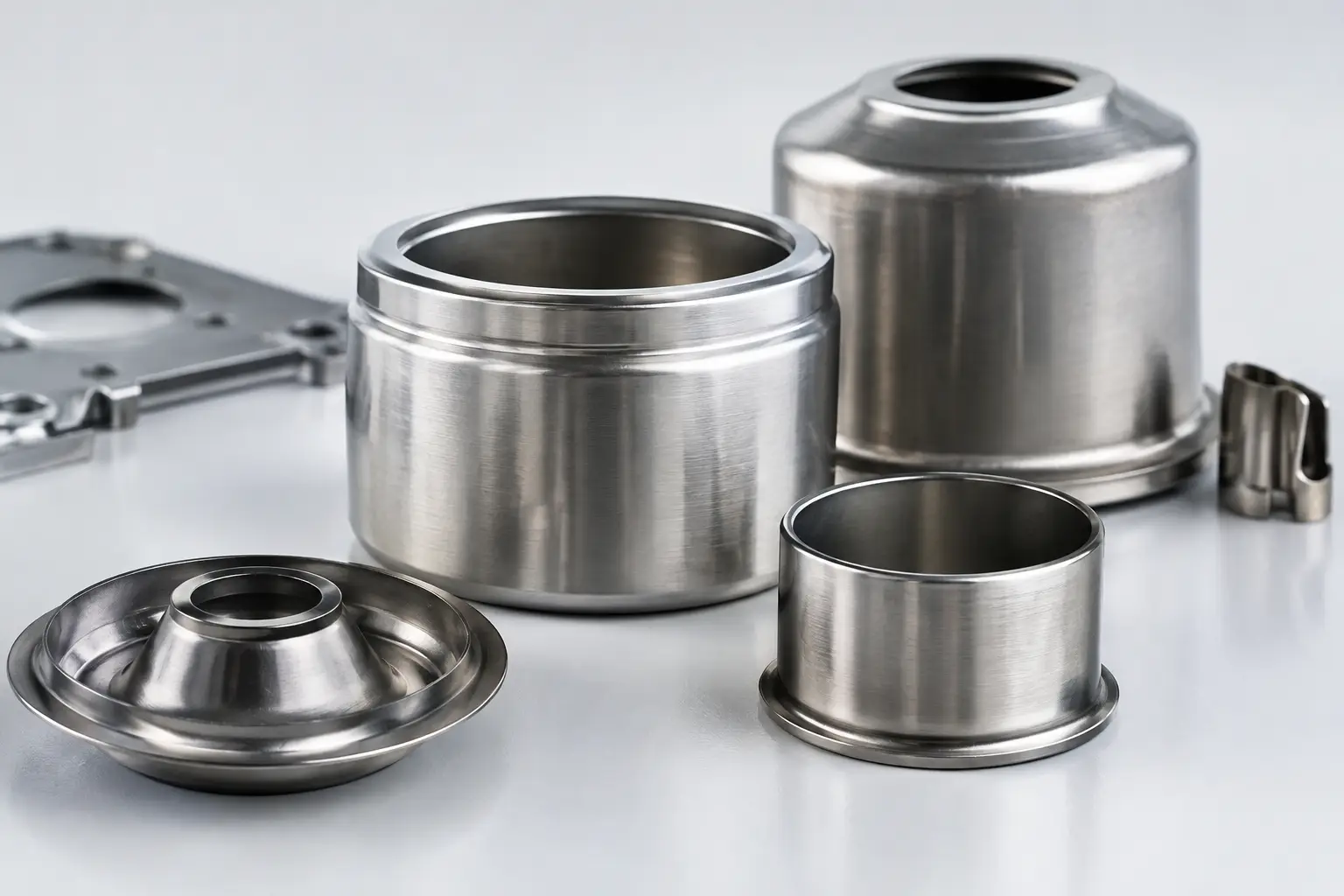
A small metal cup can determine whether a medical device seals correctly, whether a sensor remains protected in service, or whether an automotive assembly reaches its cost target. Deep drawn components are often modest in appearance, but their geometry, material behaviour and process route demand serious engineering attention. When specified well, they deliver repeatable high-volume precision with minimal material waste and fewer assembly steps.
For design engineers and technical buyers, the question is rarely whether a part can be formed. The useful question is whether it can be drawn reliably at the required tolerance, in the intended material, at a production volume that supports the tooling investment. That is where early manufacturability input earns its place.
What makes deep drawn components different?
Deep drawing forms a flat metal blank into a hollow three-dimensional shape by pulling it through a die with a punch. The process is particularly suited to cups, sleeves, cans, housings, caps, shields and other parts with a closed end and comparatively deep walls. Depending on the part geometry, the material may be drawn in more than one stage, then redrawn, ironed, trimmed, pierced or formed further.
The distinction matters because a deep-drawn part is not simply a bent sheet-metal part. Material must flow into the die in a controlled way. Too much restraint can cause tearing. Too little can lead to wrinkling. Wall thickness, corner radii, draw depth and the grain direction of the starting strip all influence the result.
For suitable geometries, the process has compelling advantages. It can produce thin-wall parts with excellent repeatability, high production rates and low scrap compared with machining a similar hollow shape from solid stock. It also supports features that can reduce downstream assembly work, such as flanges, beads, locating details or pierced openings.
The trade-off is that deep drawing is tooling-led. It is rarely the sensible route for a handful of prototype parts unless the programme is expected to progress into repeat production. A formed tube, machined part, metal injection moulded component or multi-piece fabrication may be a better fit in some cases. Good engineering starts by comparing the realistic options, not by forcing every hollow shape into one process.
Start with the function, not the drawing
The best component discussions begin with what the part must do in its assembly. Is it a protective enclosure for electronics? A hermetic or near-hermetic cover? A guide for a spring or plunger? A shielding can? A miniature reservoir? Each use case puts emphasis on different characteristics.
A sensor housing, for example, may need controlled wall thickness, precise openings and electromagnetic shielding. A medical component may prioritise cleanliness, burr control, surface finish and traceability. An automotive subassembly may place greater weight on cycle time, joining features and stable output over millions of pieces. The nominal dimensions remain important, but they are only part of the specification.
This functional view also helps identify which dimensions genuinely require tight tolerances. Holding every feature to the tightest possible limit adds tool complexity, inspection effort and cost without necessarily improving performance. A more effective approach is to define critical-to-function dimensions, datum strategy and acceptable variation in the context of the mating parts.
Geometry that supports reliable drawing
Deep drawing works best when the component geometry gives the material room to flow. Generous radii at the transition between the base and wall are generally more draw-friendly than sharp internal corners. A consistent wall section is usually easier to control than abrupt thickness changes, although local features can often be created in subsequent operations.
Depth relative to diameter is another key consideration. A shallow cup may be made in a single draw; a long, narrow sleeve may require several draws, with intermediate annealing in some materials. That does not make the part impractical, but it changes tooling, process control, lead time and piece price.
Features such as holes, slots, threads, louvres and external forms require similar judgement. Piercing after drawing often avoids distortion, while certain details may be more economical to add in a progressive sequence. Threads may be rolled, formed, tapped or supplied through a separate interface component. The right answer depends on the feature, material, required strength and annual demand.
Material selection is a forming decision
Stainless steel, low-carbon steel, aluminium, brass, copper, nickel alloys and specialised strip materials can all be used for deep-drawn components. Their suitability is not defined by corrosion resistance or conductivity alone. Elongation, work-hardening behaviour, surface condition and thickness tolerance matter directly to the draw process.
Stainless steel is frequently selected for corrosion resistance, hygiene and strength, particularly in medical, analytical and demanding industrial environments. Yet its forming behaviour must be considered alongside the required depth and radii. Aluminium can offer low weight and good formability, but may need careful handling where surface marking or stiffness is critical. Copper and brass bring conductivity and useful forming characteristics, although their cost and finishing requirements must be assessed.
Strip quality is equally important. Variations in thickness, mechanical properties or surface finish can appear later as inconsistent forming behaviour. For high-precision programmes, the specification should cover more than a generic material grade. It should define the condition, thickness range, surface expectation and any relevant compliance or traceability requirements.
Finishes and coatings also need to be planned in the correct order. Plating before forming may be appropriate for some applications, but it can crack or mark under severe deformation. Post-form coating may protect the completed part more effectively, while masking, contact points and dimensional build-up require careful coordination. There is no universal rule, only the need to treat forming and finishing as one manufacturing plan.
Tolerances require a process-aware conversation
Deep drawing can achieve impressive consistency, especially at volume, but not every dimension behaves like a turned diameter. The punch, die, material springback and trimming operation each influence the finished part. Height, outside diameter, wall thickness, concentricity, roundness and feature position may need different control methods.
A drawing that identifies tolerances without datums or measurement conditions can create unnecessary ambiguity. Consider a small cylindrical housing: should diameter be inspected free-state or supported on a gauge? Is height measured from the formed base to the trim edge? Which feature establishes the assembly axis? These details influence both capability and inspection strategy.
Where tolerances are especially demanding, it may be appropriate to combine deep drawing with secondary sizing, coining, reaming, machining or laser processing. This hybrid route can preserve the material and volume benefits of drawing while applying tighter control only where it delivers value. It is often a more sensible choice than machining the entire part from bar stock.
Tooling economics should be discussed early
Tooling is the point where an apparently simple component becomes a project decision. A production tool may include blanking, drawing, redraw, trimming, piercing and forming stations, each designed around the target material and output. The upfront cost can be substantial, but it is spread across volume and is frequently justified by lower cycle times, material efficiency and consistent part quality.
Forecast volume, programme life and change risk should therefore be discussed openly. A low-volume product with an uncertain design may benefit from a simpler tool route or an interim process. A stable, long-running programme deserves a tool designed for durability, maintainability and repeatable capability. Trying to optimise only for the first purchase order can be expensive later.
Tool ownership, spare inserts, maintenance expectations and validation samples also belong in the early conversation. For regulated or safety-critical applications, process documentation, first article inspection and change control should be agreed before production approval, not recovered after a problem appears.
From concept to production-ready part
The practical route begins with a drawing, model or even a sketch, provided the functional requirements are clear. A technical review can then assess draw feasibility, material options, critical features and likely secondary operations. Early feedback may recommend a radius change, a revised hole position, a different wall thickness or a simpler datum arrangement. Small changes at this stage can prevent a major tooling revision later.
Once the concept is aligned, prototype or pre-production samples establish whether the part performs as intended. This is the stage to test fit, joining, leak performance, surface requirements and assembly handling, rather than inspecting dimensions in isolation. Production tooling and process validation can then be built around evidence rather than assumptions.
JVS supports this work as a local technical partner, coordinating specialist manufacturing capability while keeping the engineering conversation close to the customer. For teams managing several niche technologies within one product, that single point of contact can make specification decisions and project timing far easier to manage.
A deep-drawn component should never be treated as just a small cup of metal. Give the function, material, geometry and production plan equal attention, and it can become one of the most dependable parts in the assembly.
