
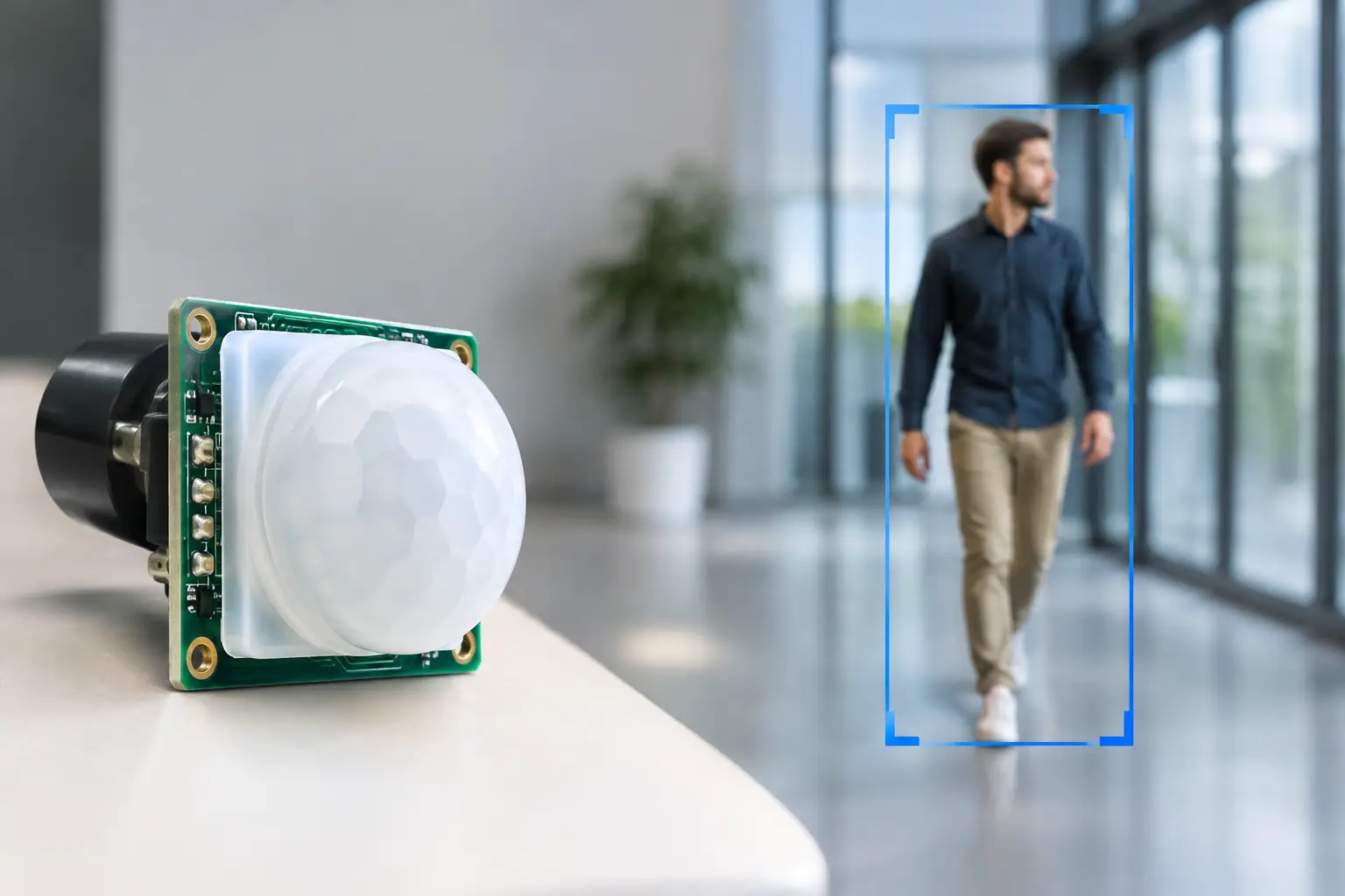
A PIR sensor can have excellent electronics and still disappoint in the field because the optical front end was treated as an afterthought. PIR lens design determines where the sensor looks, how a moving person creates a usable signal, and whether a lighting or occupancy product behaves consistently in a real installation rather than only on the bench.
For product teams developing luminaires, controls, security devices or people-counting equipment, the lens is not simply a transparent cover. It is an optical component that must be specified alongside the pyroelectric sensor, analogue front end, enclosure and intended mounting position. Getting that combination right early prevents the familiar late-stage problems: missed approaches, unwanted switching, dead areas near the fitting, or detection beyond the room boundary.
What a PIR lens actually does
A passive infrared sensor does not transmit energy. It responds to changes in infrared radiation, typically in the wavelength range associated with human body heat. A stationary person may produce little useful change at the sensor. Detection is created when a warm body moves across the sensor’s alternating optical zones.
Most PIR products use a multi-faceted Fresnel lens. Each lens facet collects infrared energy from a defined part of the scene and focuses it onto one of the sensing elements. The resulting field consists of adjacent positive and negative zones. As a person walks through these zones, the sensor receives a changing differential signal that can be amplified, filtered and interpreted as movement.
That basic principle explains why a lens cannot be selected by diameter or appearance alone. Its facet geometry defines the coverage pattern. Its focal characteristics must suit the chosen sensor. Its material and surface quality influence transmission and repeatability. A small change in any one of these variables can materially alter practical detection performance.
PIR lens design starts with the detection task
The right question is not, “What range do we need?” It is, “Who must be detected, doing what, from where, and at what mounting height?” Corridor lighting, desk-level occupancy sensing and intrusion detection may all use PIR technology, but their optical requirements are different.
A corridor application generally benefits from long, narrow zones arranged to detect cross-traffic at a distance. An office luminaire may need broad coverage with good sensitivity to modest movement within a defined area. A people-detection device may need a more controlled field of view, with intentional limits that reduce interference from adjacent spaces or activity outside a doorway.
Walking direction matters. PIR devices are commonly most sensitive to transverse movement across zones. Movement directly towards the sensor can produce a weaker signal because the person remains within a zone for longer. A well-designed lens pattern compensates where possible, but it cannot repeal the physics. If approach detection is critical, it needs to be explicitly included in the optical specification and validated in representative use.
Mounting height and angle are equally decisive. A ceiling-mounted lens designed for a 2.5 metre installation will not automatically give the same coverage at 4 metres. Zone spacing changes across the floor plane, near-field areas can behave differently, and the useful energy reaching the sensor falls with distance. The enclosure also matters: a recessed bezel, decorative trim or mechanical ribs can clip peripheral zones and create an unexpected blind spot.
Coverage drawings need practical interpretation
A coverage diagram is a useful engineering tool, not a guarantee that every point inside an outline will perform identically. Published ranges may be based on a defined target, ambient condition, mounting position and walking direction. A seated person making small movements presents a very different target from an adult walking across an open area.
This is where product development benefits from translating a headline requirement into testable scenarios. For example: detect a person entering through a door at six metres; maintain occupancy during keyboard and desk activity; ignore movement through a glazed partition; avoid triggering from a heater outlet. Such statements give optical, mechanical and electronics teams a common definition of success.
Optical zones, sensor geometry and signal quality
The lens and sensor operate as a system. Dual-element PIR sensors are widely used because they respond to the difference between the infrared energy falling on each element. The lens must direct the scene appropriately onto those elements to create alternating signals as the target moves.
The sensor’s active-area size, element separation, package position and optical axis affect the required lens geometry. A lens designed around one sensor package may not deliver the intended zone pattern when paired with another, even where both sensors have similar headline sensitivity. Mechanical stack-up tolerances also become relevant quickly. If the sensor-to-lens distance drifts from the focal design position, energy concentration and zone definition can degrade.
Signal-to-noise ratio is the practical measure that links optics with electronic performance. More infrared energy on the sensor can improve the useful signal, but a very aggressive optical design may also enlarge the field, increase sensitivity to unwanted activity or make the product more exposed to thermal disturbances. Wider coverage is therefore not always better coverage.
The same trade-off applies to zone density. More zones can support finer motion discrimination, particularly at longer distances, but the resulting signals may become weaker or more sensitive to alignment, target speed and environmental variation. The best pattern is the one that gives sufficient contrast for the real movement profiles the product must recognise.
Material choice is a performance decision
PIR Fresnel lenses are commonly moulded from polyethylene because it provides good transmission in the relevant infrared region and can be formed economically into detailed Fresnel structures. Yet “polyethylene lens” is not a complete specification. Grade, thickness, additives, pigment, mould quality and surface condition all influence optical behaviour and production consistency.
Transmission must be considered alongside environmental durability. Lighting products may spend years near heat sources, in humid buildings or in locations exposed to cleaning chemicals and UV light. The lens must retain its shape and optical properties across the expected temperature range. It must also fit the product’s visual and mechanical requirements, including any need for a discreet appearance, a low-profile form or controlled illumination from nearby LEDs.
Lens thickness presents another engineering balance. A thin lens may support better infrared transmission and lower material use, but it can be less stable during moulding, assembly and service. A thicker section may be mechanically preferable while absorbing more of the desired infrared energy. The suitable answer depends on the optical path, the enclosure design and the capability of the chosen manufacturing process.
Design the lens with the enclosure, not after it
A lens that performs well as an isolated sample can behave very differently once installed. Internal reflections, sensor cavity geometry, window edges and even the finish of nearby plastic surfaces can affect the radiation reaching the sensing elements. Mechanical features that appear harmless in CAD can obstruct a critical edge zone.
The sensor cavity should control stray infrared paths while preserving the intended field of view. The lens needs repeatable location features, and the sensor PCB needs a stable datum relative to the lens. Where a product uses a visible-light diffuser or illuminated housing, teams should also assess whether local heating from LEDs or drivers creates thermal modulation that reaches the PIR assembly.
This is particularly relevant in smart luminaires. LED thermal management, driver placement and PIR performance cannot be developed as separate workstreams until the final prototype. A sensor placed too close to a changing heat source can suffer from false events or reduced sensitivity, even with a well-designed lens.
Validate in conditions that resemble the installation
Optical simulation and coverage modelling are valuable early tools, especially for comparing lens patterns and identifying blocked views. They should then be followed by physical trials. PIR performance depends on human movement, background temperature, airflow, mounting geometry and electronic filtering, all of which interact in ways that a single model may not fully capture.
A meaningful test plan includes more than a person walking through the centre of the pattern. Test at boundaries, close to the product, at the maximum required distance and along different approach paths. Include slow movement, cross-traffic and the minimum target activity the application must recognise. Test in both cool and warm ambient conditions, because the thermal contrast between a person and the background can change significantly.
False-trigger testing deserves the same discipline. Consider sunlight, warm air from HVAC outlets, moving machinery, curtains, pets where relevant, and adjacent rooms or corridors. The goal is not to make a PIR product insensitive. It is to create a field of view that is purposeful and predictable.
From optical concept to production-ready lens
Successful PIR lens development is a cross-functional job. The optical requirement sets the direction, but manufacturability determines whether the performance can be reproduced at volume. Fresnel facets, draft angles, moulding shrinkage, part handling and inspection criteria all need consideration before a design is frozen.
For bespoke projects, early discussion with an experienced lens specialist can save several iterations. It allows the team to assess available standard patterns, adapt a proven optical platform where appropriate, or develop a custom configuration when the application genuinely needs it. Standard lenses can shorten time to market; custom optics can provide better field control, product differentiation or a fit for an unusual mechanical envelope. Neither route is automatically superior.
At JVS, the useful starting point is a technical conversation that brings together the intended detection behaviour, sensor choice, mounting constraints and production objectives. The aim is straightforward: turn the required coverage pattern into a lens solution that can be made consistently and supported locally.
A PIR lens is a small part with a large influence on user trust. Specify the real detection task first, validate the full optical-mechanical-electronic assembly, and the finished product is far more likely to switch on at the right moment and stay quiet when it should.
